Triaxial

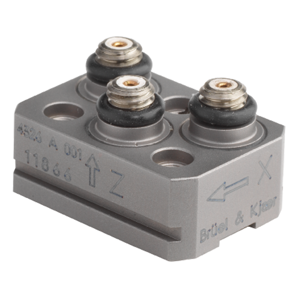
B&K Type 4326-A-001 Miniature Triaxial Piezoelectric Charge Accelerometer, With Slots, Excl. Cable
Types 4326-A and 4326-A-001 are triaxial piezoelectric ThetaShear® patented accelerometers with three independent outputs for simultaneous high-level measurements in three mutually perpendicular directions. Each transducing element is individually calibrated.
USE SCENARIOS
- General purpose, multi-axis vibration and shock measurements on low-mass structures and in confined spaces
To avoid triboelectrical noise originating in the connector and to provide maximum measurement reliability and confidence, special attention has been paid to the three connectors. Both accelerometers feature three separate, rugged 10 – 32 UNF connectors.
CHARACTERISTICS
This piezoelectric accelerometer may be treated as a charge source. Its sensitivity is expressed in terms of charge per unit acceleration (pC/g).
The ThetaShear design involves a slotted cylindrical stanchion holding a central seismic mass, flanked by two piezoelectric plates. This assembly is clamped rigidly by the cover. To ensure optimum accuracy and reliability, no bonding agent other than molecular adhesion is required to hold the assembly together. The ThetaShear design provides a combination of highest measurement stability, excellent sensitivity-to-weight ratio and low sensitivity to extraneous environmental effects.
A remarkable feature of the ThetaShear principle is the fact that the transverse resonance frequency will always be found outside the 10% frequency limit. This ensures minimum interference from orthogonal vibration components in the useful frequency range of the accelerometer. The ThetaShear design also provides excellent immunity to other environmental effects such as base strains, magnetic sensitivity and acoustic fields.
VERSION
The piezoelectric element used, is the PZ 23 lead zirconate titanate element. Type 4326-A and 4326-A-001 differ from each other in weight and temperature range. The housing is aluminium for Type 4326-A and more robust, but heavier titanium for Type 4326-A-001.
MOUNTING
Special effort has been put into making mounting as flexible as possible. For fast and easy mounting, Mounting Clips UA-1408, UA-1473 and UA-1474 can be used. Five of the six surfaces can be used for mounting with adhesive cement or mounting wax. Where threaded holes can be provided in the test piece, Type 4504-A can be mounted from the top via mounting holes in the base. The base can accommodate three M2 screws for top mounting.
Ground loop noise, particularly troublesome in multichannel measurements, is avoided by electrically insulating the sensing elements from the common body. Both Type 4326-A and Type 4326-A-001 feature this electrical insulation with respect to signal ground and have a resistance of more than 10 MW.
The electrical insulation of Type 4326-A comes from its fully hard anodised common body, with insulation at the three cylindrical mounting holes. The hard anodised mounting surfaces provide additional insulation.
The electrical insulation of Type 4326-A-001 comes from the special mounting technique for the three sensing elements. A non-conductive glue is used to bond the sensing elements to the holes in the common body. The three individually insulated sensing elements ensure that no ground loop currents are induced in the measurement setup. This is particularly beneficial in engine test applications.
CABLE CLAMPING
When using miniature accelerometers, the accelerometer cable can affect the measurement result because of forces exerted by the cable on the accelerometer connector. This can then cause amplitude irregularities in the output from the accelerometer at frequencies up to approximately 200 Hz. This can be reduced by using a flexible cable. To effectively reduce the problem at low frequencies, it is generally recommended to clamp the cable. One way of doing this is to make a small loop in the cable close to the accelerometer (max. diameter 30 mm) and clamp the cable beside the base of the accelerometer with mounting wax or double-sided tape. This also reduces the possibility of dynamically induced noise generated by the cable.
CALIBRATION
The sensitivity given in the calibration chart has been measured at 159.2 Hz with an acceleration of 10 g. For a 99.9% confidence level, the accuracy of the factory calibration is ± 2%.
Frequency range: 1 – 8000 Hz
Temperature: -55 – 230 C
Weight: 17 gram
Sensitivity: 0.316 pC/ms^-2
Residual Noise Level in Spec Freq Range (rms): ±0.56 mg
Maximum Operational Level (peak): 3000 g
Electrical connector: 10-32 UNF
Mounting: Screw Clip
Output: Charge-PE
Unigain: No
Triaxial: Yes
TEDS: No
Applications: Miniature, General Purpose, Vibration Test
Resonance frequency: kHz
Maximum Shock Level: (± peak)g


