
Multi-Axis
3AFM Series 3-Axis Force/Torque Load Cells

Description
Force/Torque: 4.5lbf/0.001lbf-in to 1124lbf/0.57lbf-in
Force/Torque: 20N/0.2Nm to 5000N/100Nm
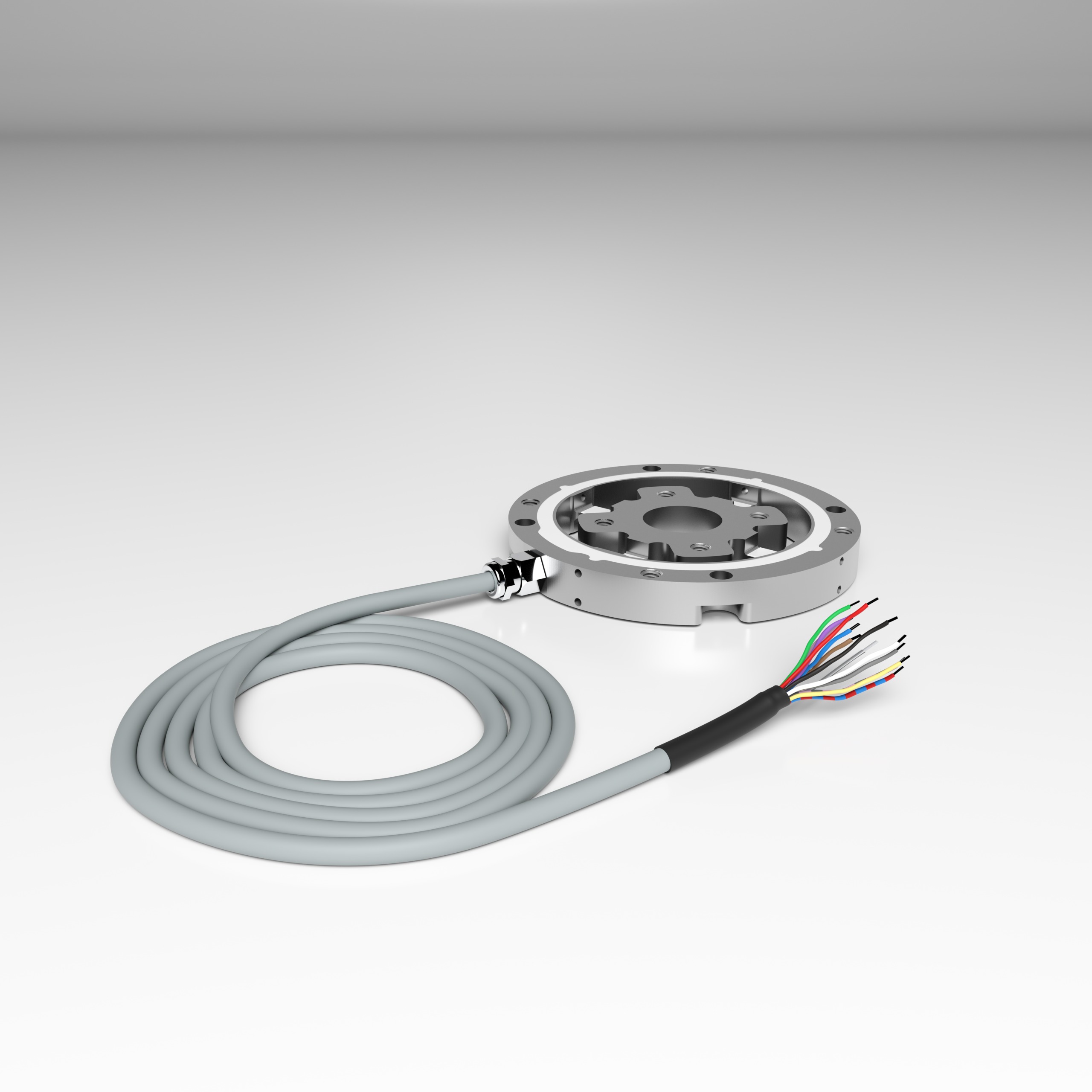
The 3AFM Series 3-Axis Force/Torque Load Cells are ideal for inspection tasks in quality assurance and material testing due to their compact and low-profile design, with a thickness of just 12–14 mm. This precision force sensor features four independently wired strain gauge measuring springs. The strain gauge signals enable the calculation of axial force (Fz) and bending moments (Mx and My) around the x- and y-axes. Additionally, the sensor’s design allows for the determination of horizontal forces (Fx and Fy) and bending moments based on the distance of the force transmission from the sensor surface. A simple calibration matrix ensures the easy processing of sensor signals, allowing for accurate conversion into forces and moments.
Models 3AFM70 and 3AFM110 are available.
Features and Benefits
- 70 or 100 mm Diameter
- Low 12 or 20mm Height
- Measures Fx, My, Mz
- Stainless Steel or Aluminum Alloy Construction
- IP 66
Specifications
3AFM70 3-Axis Force/Torque Load Cell
| ACCURACY – (MAX ERROR*) | ||
| Nonlinearity – %FS | ±0.1 | |
| Hysteresis – %FS | ±0.1 | |
| Creep, in 30 min – % | ±0.1 | |
| TEMPERATURE | ||
| Effect on Zero – %RO / deg | °C | ±0.05 |
| Effect on Output – % / def | °C | ±0.05 |
| Operating Range | °C | -20 to +70 |
| °F | -4 to +185 | |
| ELECTRICAL | ||
| Rated Output (Nominal) – mV/V | 0.5 | |
| Max. Excitation Voltage – V | 10 | |
| Zero Balance – mV/V | <0.1 | |
| Input Resistance, x, y, & z axis – Ω | 350 | |
| Output Resistance, x, y, & z axis – Ω | 350 | |
| MECHANICAL | ||
| Rated Capacity (FS) | N | ±2,±10, ±20, ±50 |
| lbf | ±0.44, ±2.24, ±4.49, ±11.24 | |
| Cable length | m | 3 |
| ft | 9.8 | |
| Material | Aluminum-Alloy | |
| Total Weight | g | 85 |
| lbs | 0.18 | |
| Safe Overload – %CAP | 150 | |
| Ultimate Overload – %RO | 300 | |
| Dimensions | Ø 70 mm x 12 mm | |
| Standard Connector | SubD44HD | |
| Protection Level | IP66 | |
| ECCENTRICITY AND MOMENT* | ||
| x into y – %FS | 0.5 | |
| y into x – %FS | 0.5 | |
| z into x – %FS | 1 | |
| z into y – %FS | 1 | |
| x into z – %FS | 1 | |
| y into z – %FS | 1 | |
| Influence of Eccentric load %FS/2Nm | 0.5 | |